Edit Calculation Points
|
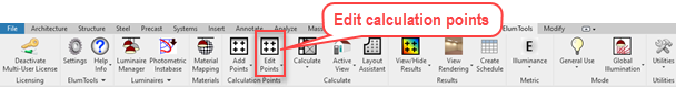
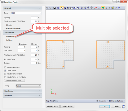
Either select the Edit Calculation Points command followed by the calculation point family marker of interest, or select the family marker(s) in Revit followed by the command button on the toolbar. You can select multiple calculation points grids using the Multiple option from the toolbar, or, you can select the markers in Revit and then click on the main Edit Calculation Points button. It can also be handy to window across a number of marker instances and use the Revit Filter command to only select "Generic Models".
When a calculation point family marker is selected, the same dialog used to set the calculation point parameters originally is presented to make any required modifications. If you have selected multiple boundary types (Rooms and Regions for example), any changes made will be applied to all boundaries.
When calculation point parameters are changed, the calculation is invalidated and the edited grids must be recalculated.
|
|
Calculation Point Spacing Check (optional)
|
ElumTools has an optional check for calculation point spacing designed to warn against points that may be too far apart to yield informative results for the lighting application. This check must be enabled* from System Settings (set Validate Calc Point Spacing to True).
*The setting is disabled by default.
When enabled, editing calculation points and changing the point spacing will trigger the internal check. The spacing check happens when you attempt to close the Calculation Points dialog.
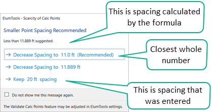
The spacing check formula is based on British Standard document BS EN12464. If the point spacing falls outside of the formula boundary, ElumTools will respond with the choices shown in the dialog to the right and discussed below. |
|
-
Option one (on top) is rounding down from the formula result to the nearest whole number and is the recommended choice.
-
Option two (middle) is the exact result of the formula calculation.
-
Option three (bottom) is the value you have entered.
The BS EN12464 standard recommends calculation point spacing based on the following formula:
(metric meters) Point spacing = 0.2 x 5log10(d)
(Imperial feet) Point spacing = 0.286 x 5log10(d)
d = the longer dimension of a rectangular grid, in meters or feet.
Notes
-
For rectangular grids, d is the longer dimension of the calculation area. However, if the ratio of the longer to the shorter side is 2 or more, then d becomes the shorter dimension.
-
For non-rectangular girds, the XY-axis aligned bounding box of all geometry is used to determine d.
Masking
|
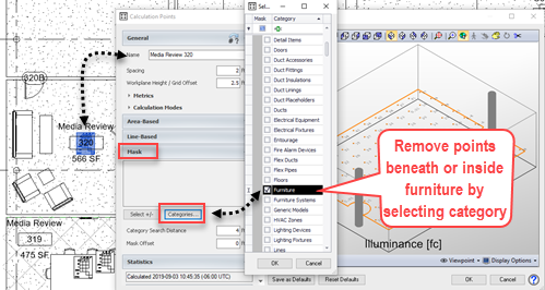
Unwanted calculation points can be removed at any time using the Edit Calculation Points command. Open the Mask section of the Edit Calculation Point dialog and click either the Select +/- or Categories buttons.
Select +/- will allow you to click on objects in the current Revit view to be used as masking boundaries.
Categories (shown) will open up a secondary window where you can select a Revit category to provide the masking boundaries.
See also Masking Calculation Points topic. |
|
Statistics
|
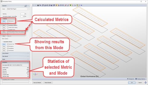
When a previously calculated point family is selected, the calculation results will appear in the edit dialog. Statistics are shown in the Statistics section on the left and point by point values in the viewer on the right. The "Calculated" field will display the time and date of the last calculation.
If you have selected multiple Metrics in General Use mode (illuminance, luminance, etc.) to be computed for the subject grids, you can switch the viewer display between the different metric results. Open the Metrics section and click the View button for the grid of interest to be displayed.
If you have mode-specific metrics selected such as PPFD or Daylight Factor, the quantities are only computed when the calculations are run in that mode. If you wanted to toggle between illuminance and PPFD for example, the calculations must have been run in both modes and the appropriate mode must be selected to View as well (adjacent capture).
|
|
Selecting Planar Face points
The Planar Face calculation points family marker may not be visible in every view. The default height of the family marker is 7.5' so the marker is typically visible and selectable in a ceiling plan or floor plan view with default limits. If not visible, it may be easiest to select the family marker in a section or 3D view. If the points are on a desktop they may be visible in a floor plan view but not a ceiling plan view due to clipping planes for these views.
|
|